Design of Suspension Bridge Using Staad Pro
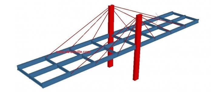
Stays can be used to support orthotropic bridge decks which consists of continuous girders. The stays which are inclined cables passing over or pinned to the piers are attached to the girders and forms part of the supporting system of the bridge deck. Wide application of cable stayed bridges have been achieved recently due to the development of high strength steel, improved bridge deck systems, and analytical tools/software. In this article, we intend to explore the applicability of Staad Pro software (v8i) in the non-linear analysis of cable-stayed bridges under moving traffic load. This will be evaluated using a simple bridge deck model.
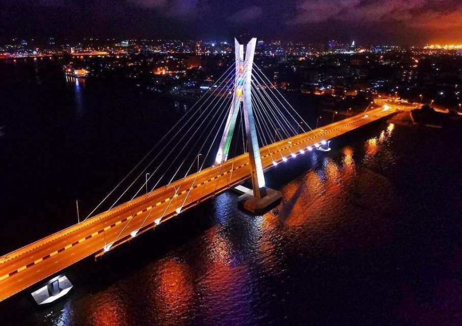
In cable-stayed bridges, the tension members (inclined cables) should be able to develop high degree of stiffness due to prestress under the dead load of the brdige deck, with additional capacity to take loads from the live load. In the example adopted in this article, the radial or converging cable stayed system was adopted, which is deemed the most efficient arrangement due to its ability to carry the maximum component of the dead and live load, while keeping the axial load in the bridge deck to a minimum. An example of this arrangement is the Ikoyi-Lekki link bridge in Lagos, which is the first cable-stayed bridge in West Africa.
In Staad Pro, the simplified arrangement adopted is shown below.
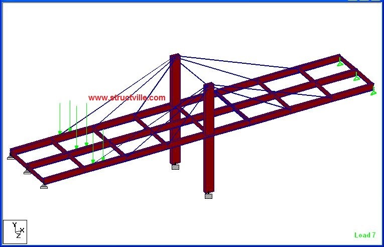
The properties of the sections used in the analysis are as follows;
Pylons – Concrete (1000 x 500)mm
Main girders – Steel (UB 762 x 267 x 147)
Cross girders – Steel (UB 457 x 152 x 60)
Stays – 50 mm diameter steel cables
The pylons were placed on a fixed support, while the two ends of the bridge deck were placed on pinned and roller support respectively. The geometry and dimensions of the bridge components are shown below;
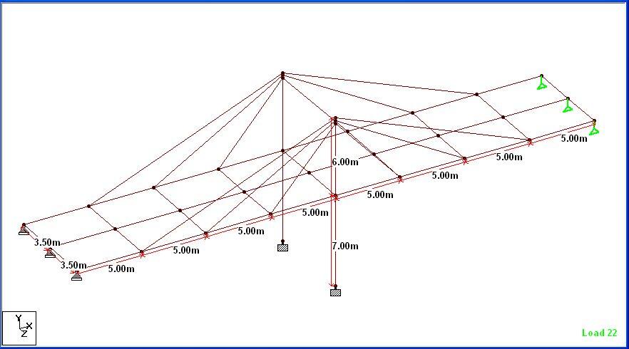
The load cases that were considered in the model are the self weight of the bridge and moving traffic wheel load. Since the deck slab was not modelled, it was not accounted for in the self weight of the bridge. Also, the UDL components of traffic action and full wheel load recommendations according to EN 1991-2 were not considered. Therefore, the results from this analysis are only representative of the assumptions made, and may not fully reflect the behaviour of cable-stayed bridges.
Read Also…
Non-linear analysis of cable-stayed structures on Staad Pro
Static analysis of suspension bridge structures
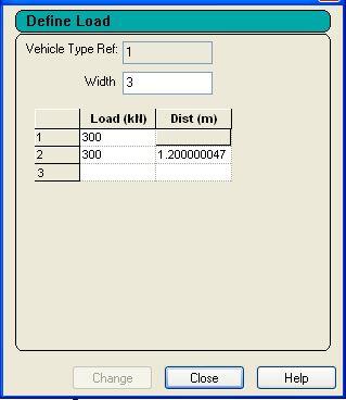
A tandem load of 4 wheels (300 kN each) with a width of 3 m and longitudinal spacing of 1.2 m was used in the model, and applied at the centre of the bridge.
Linear Analysis Results
When analysed on Staad Pro using linear elastic analysis, the bending moment, shear forces, axial force, and displacements were obtained due to the self weight and the moving load.
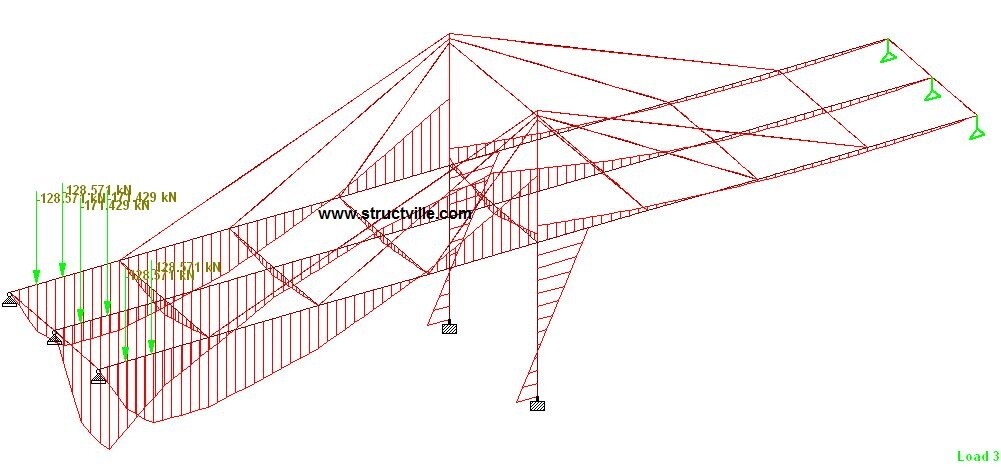
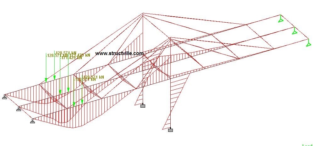
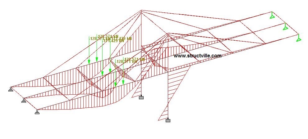
The variation of the bending moment as the wheel load travels on the bridge deck is shown in the figures below;
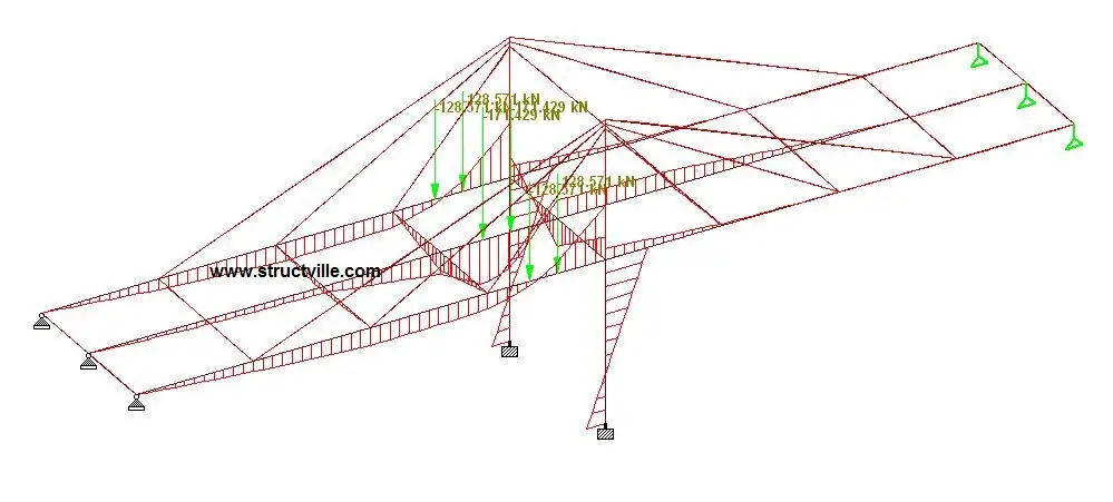
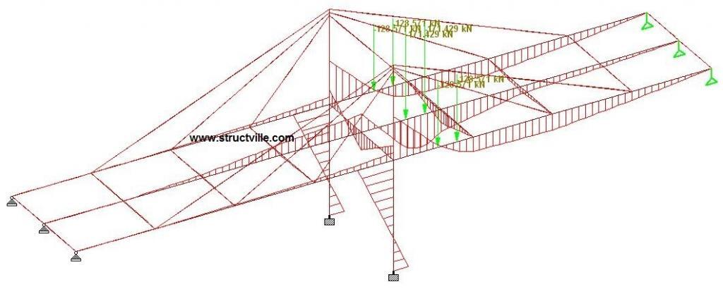
The deflection and bending moment of the structure under self weight is shown below. Note that this linear analysis was carried out under zero initial tension in the cable.
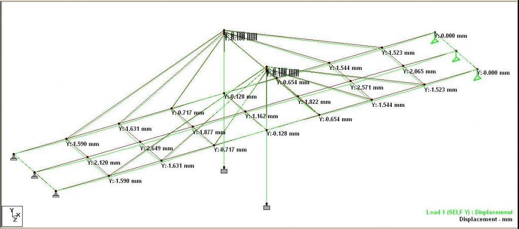
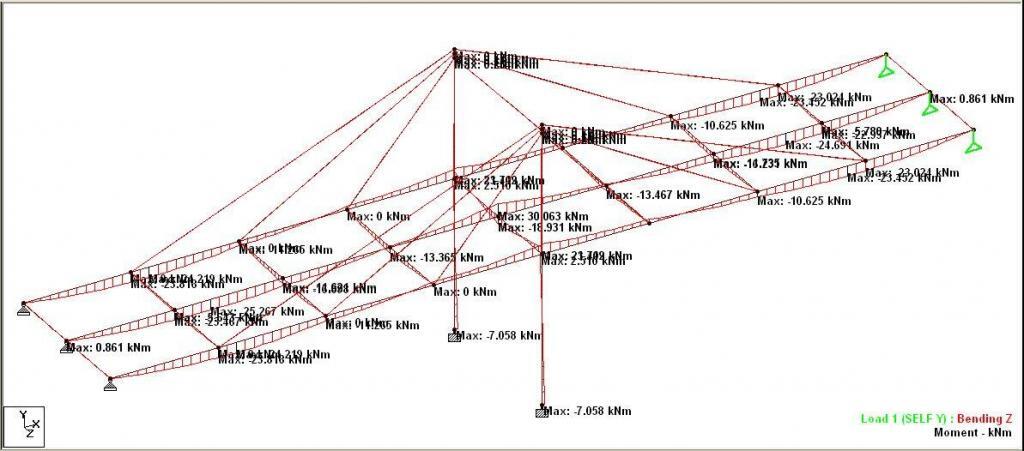
The tension in the cables are;
Cable 1 (closest to the piers) = 19 kN
Cable 2 (intermediate) = 22.3 kN
Cable 3 (farthest from the pier) = 11.2 kN
Non-Linear Cable Analysis
A preliminary attempt to run a non-linear cable analysis for moving load using Staad Pro was not successful. However, a non-linear analysis result was obtained for the self weight of the bridge members. The non-linear cable analysis command used is shown below. You can click HERE to see the definition of the terms. An initial tension force of 0.5 kN was applied to the cables.
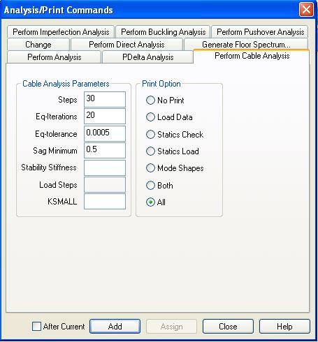
Using the parameters above, the self weight load case converged 100% with zero errors and zero warnings. The non-linear displacement of the structure under self-weight is shown below.
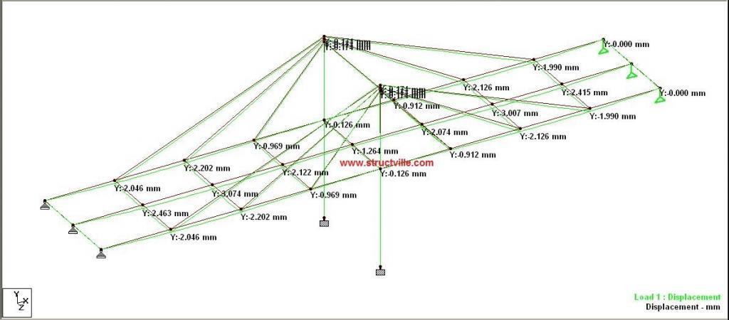
The value of deflection was observed to be higher than the deflection obtained from linear analysis. The tension in the cables are shown below, but were observed to be lesser than the result obtained from static linear analysis.
Cable 1 (closest to the piers) = 17.3 kN
Cable 2 (intermediate) = 16.5 kN
Cable 3 (farthest from the pier) = 7.7 kN
The maximum moment under the self weight for non-linear analysis is shown below;
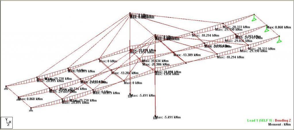
Further analysis showed that the result of non-linear cable analysis is heavily influenced by 'Sag Minimum'. The closer 'Sag Minimum' is to 1.0, the closer the non-linear result is to linear analysis and vice versa. 'Sag minimum' is a factor used to account for sagging in the cable when the tension is low. This is achieved is Staad Pro by modification of the modulus of elasticity of the cable. However, if the value is too low, the analysis will not converge properly.
Since the non-linear cable analysis of the structure was not successful for moving load, I recommend you run linear analysis of the moving load and obtain the critical load locations. Later, you can apply the loads statically at the critical location, and run the non-linear cable analysis under a single load case. A example of this process is shown below.
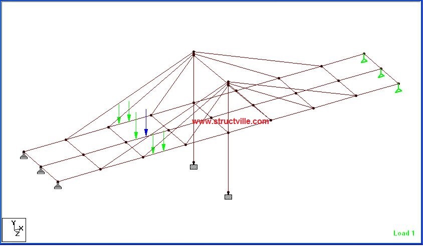
The wheel load shown in the figure above has been applied statically, and the load case was combined with the self weight of the structure. Using the same non-linear parameters used above, the analysis results are as follows;
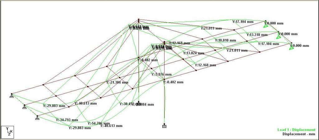
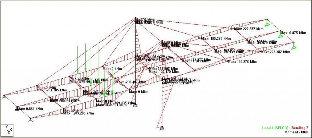
The tension in the cables at the left hand side of the piers are;
Cable 1 (closest to the piers) = 259 kN
Cable 2 (intermediate) = 185 kN
Cable 3 (farthest from the pier) = 0
The tension in the cables at the right hand side of the piers are;
Cable 1 (closest to the piers) = 14.8 kN
Cable 2 (intermediate) = 76 kN
Cable 3 (farthest from the pier) = 195 kN
A better option for handling this can as well be recommended.
You can book a zoom meeting request for training or discussion with the author by sending an e-mail to ubani@structville.com or Whatsapp message to +2347053638996
Design of Suspension Bridge Using Staad Pro
Source: https://structville.com/2020/05/analysis-of-moving-load-on-cable-stayed-bridges-using-staad-pro.html
0 Response to "Design of Suspension Bridge Using Staad Pro"
Post a Comment